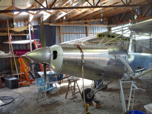
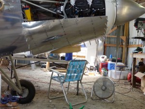
I picked up where we left off last night , attaching the lower right cowl sheet metal. I took a few pictures of it all together, just because it looks so much more like an airplane.

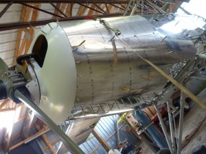
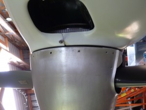
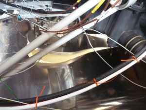
From there I reinstalled the carburetor so that I could start cutting the hole for the airbox. Note that in this series of pictures the FAB top is upside-down. This ended up being a problem later, so I would encourage you to not do the same! I started with aligning the left/right angle. I’ve flown Lycoming-powered airplanes for years, but it took building one for me to notice that the carburetor doesn’t sit on the airplane’s centerline. As others have noticed, the choice is to either keep the axis of the airbox parallel to the airplane’s axis, or to angle the airbox towards center of the nose bowl. I chose a mixture of the two, with a bit more of option 2. I marked the centerline on the lower cowl, then tried to approximate where the outer scoop would fall. To clarify, the intake includes the fiberglass FAB (Filtered Air Box), which attaches to the carburetor, and an outer fiberglass scoop, which attaches to the cowling. The FAB shakes with the engine, while the scoop shakes with the airframe. Since the front of the FAB is aft of the outer scoop by a couple of inches, positioning the front of the FAB on the centerline of the airplane will put the scoop entrance on the right side of the centerline. This is undesireable for both aerodynamic and aesthetic reasons. This was why I preferred to err to the left. To get started, I rested the FAB top on the oval top plate:

This picture shows the same situation from the side:
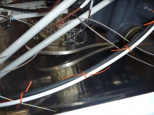
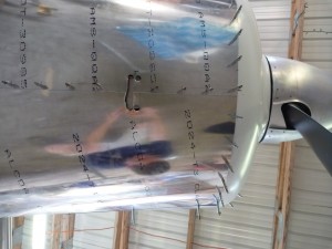
I used a step drill to create large holes that would make nice round corners on the finished hole. In the end this didn’t matter very much since I enlarged the hole beyond those originals.

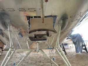
From there my strategy was to enlarge the hole a little bit at a time until I had at least an inch of clearance. That airbox is going to be moving around quite a bit relative to the cowl.
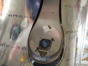
This picture has a couple of problems with the top oval plate. I ended up remaking this part for a couple of reasons. First, note that the carb sump has a little finger that sticks over to the left. After lots of research and hand-wringing, I decided to remove that part of the carb. I used the grinding wheel to get most of it off, then the belt sander finally the die grinder. You’d never know it was there! Also, since I was doing all of this work with the FAB top on upside down, none of my holes lined up once I flipped it back over.
The next few pictures are just to show where the FAB falls on the Bearhawk cowl.
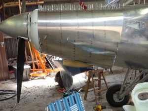
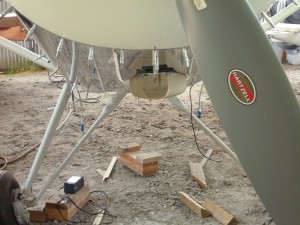
The next step was to bend the FAB top to bring the front end of the assembly up closer to the cowl.
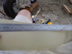
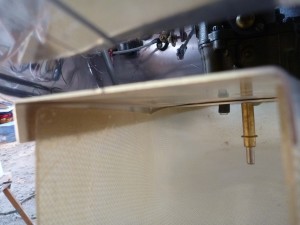
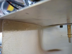
I think this box is much nicer than the other options available. It is a much more compact and durable design, and it uses a locally-available filter that is reusable. Another advantage is that carb heat is filtered air, which is good for we grass airport residents.