I finished up the p-leads today for the Bendix mags. These mags require a special terminal, and I was able to find a used set of terminals in good shape. I used a single-conductor shielded cable, which was especially troublesome to strip and separate. The weave of the shield is very tight and it took a couple of attempts to get a good result. I added a bit of heat shrink to the empty shield right where the center conductor exits, and then another layer of heat shrink over the whole cable at that junction also. Hopefully this will be enough strain relief to keep the shield from breaking. You’ll also notice that I separated about a 4″ length, but cut the center conductor shorter. This is to allow for a cleaner installation, since the locations on the back of the mag are also staggered.
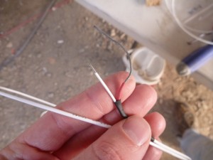
I added the outer threaded ring, then the metal piece, then the insulating piece. Then I added the little washer, bent the very ends of the conductor, and soldered the washer in place. Obviously it’s important for me to get the sequence correct here, since the other parts can’t go over the soldered end.
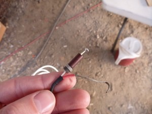
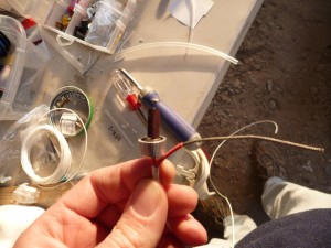
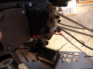
I crimped a ring terminal onto the shield, then used one of the screws on the back of the magneto to secure it. Here’s the whole thing:
The cockpit end was slightly different. I used 1/4″ fast-on tabs to attach the lead to the switch, but I also added a provision for the Dynon tachometer reading. The Dynon system is able to derive a tachometer indication by measuring the noise on the p-lead. The Dynon instructions specified the resistor value.
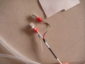
I crimped one end into the fast-on terminal and crimped a machined d-sub pin onto the other. This arrangement allows me to separate the wires going to the D-180, which may prove useful in future service. I used a female socket on one lead and a male pin on the other so that they are not interchangeable.
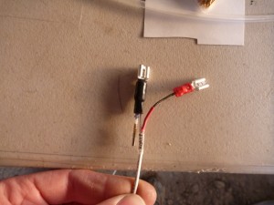
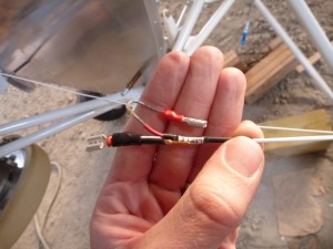
Next I connected the wire that goes from the starter switch to the starter contactor, and the wire that goes from the other terminal on the starter switch to the fuse block. This circuit works by providing 12 volts to the starter contactor terminal when it’s time to engage the starter, and that’s why it starts at the fuse block.
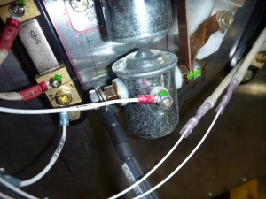
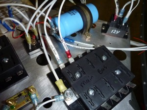
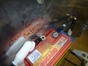
I also wired the battery contactor’s switch, the master switch. The battery contactor has a different design than the starter contactor. In the case of the battery contactor the switch lead is completing a circuit to ground. So the wire goes from the contactor to the switch, then to the ground tabs on the firewall. The contactor draws it’s current from the big terminals and thus doesn’t need a fuse.
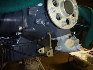
Next I started on installing the alternator brackets. Since the bracket shares bolts with the engine halves, I will have to remove the current bolts and replace them with longer alternatives.
