In the last installment you might remember that I damaged the ebus alternator by shorting it to the airframe ground. The good news is that I was able to find a replacement for just the diode, and thus reuse the circuit board and mounting hardware that I got from Bob at aeroelectric.com. I clipped the leads off of the old diode:
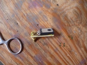
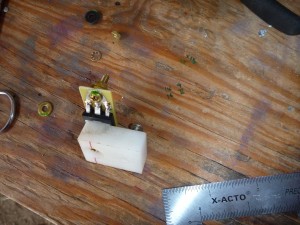
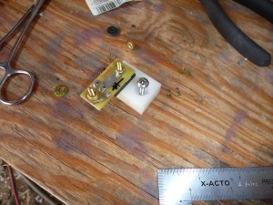
Then used the soldering iron and hemostats to remove the stubs. This seems to be the most effective way to protect the integrity of the holes, and since the old chip is trash it’s no loss. I soldered the new chip in place and devised a slightly more robust mounting method:
Here it is in place:
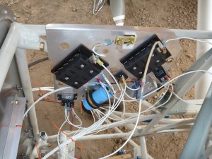
Just to check for shorts, I turned on the master switch with the battery disconnected and applied my ammeter in series with the battery and battery lead. I got a steady .686 amps, which is about right for what the battery contactor needs to keep itself open. That’s also a good number to know- I had counted on 1 amp for my load analysis. The Z13/8 system allows me to open that contactor in the event of a primary alternator failure- in that case, the ebus can be powered by the standby alternator and the main bus is shed entirely. This low-consumption configuration keeps the current demands in line with what the SD-8 can put out.
The fuse block that I’m using for the battery bus is hollow on the back. The metal parts are recessed so that they don’t short out on the firewall, but I’d rather have something other than air between the two since the feeds are protected only by the size of the wire going to the bus.
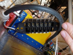
I used a little bit of high temp RTV to “pot” the back, filling in the air space and providing an extra layer of insulation. This will also keep gunk from collecting in there.
I installed a powerlet style lead on the battery so that I can hook up a battery maintaning charger more easily. I used the connector that came with the charger, but I shortened the leads considerably and crimped on new rings.
I took a few minutes to clean the dust off of the trailing edge of the wing. One of the drawbacks to our hangar arrangement is that dust flies around and settles on everything. An occasional cleaning is a small price to pay for our low overhead!
I also added the rest of the alternator brackets:

And the alternator itself:
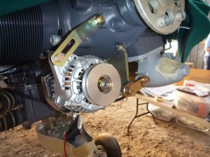
Everything lined up perfectly. Next I installed the aileron balance tubes in the ailerons and trimmed them just a hair so that they’ll fit.