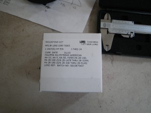
I’ve been watching the price of the engine mount rubbers for the past few months, and the trend seems alarming. In the 2008 Vans Accessory catalog, they were $40 per lug (for a total of $160). Today Vans sells them for $125 per lug, or $500 plus shipping! Yikes! I was surprised to see the cost go up so quickly. I was looking for some way to spend less, and eventually found that Jeppesen of all places sold them. Their price was well below anything else that I could find, at $88 per lug. My only explanation for this was that their price was outdated, but who knows. I was glad to save so much money. Here’s the data from the box:
Nobody seems to know how long the bolts need to be for attaching the mounts to the engine. I don’t really understand the mystery- the mounts have a center tube that gets compressed to the washers on either side. Now that I have them on hand I can measure the length of that tube and the end washers to come up with a grip length for the bolts. Here are some pictures of my measurements, in case you find yourself wondering how long the bolts should be.
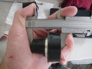
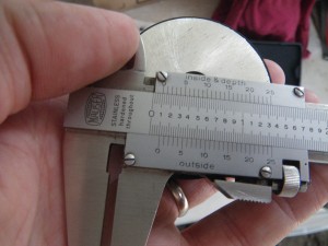
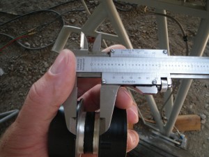

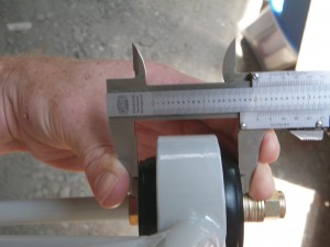
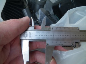
For the purpose of ordering bolts, my measurements aren’t especially accurate, since the bolts generally come in 1/16″ increments. I figured that the compressed rubber was 2.03″ and the engine lug was .93″. This makes the required grip length for the -7 bolts 2.96, not counting for any washers (and I’ll need at least one of those at 1/16″). The AN7-34 is 2 15/16″ (2.9375″), so I ordered the 7-35 with it’s 3 1/16″ grip length. That will allow for a washer or two but will keep the bolt’s threads out of the way.
With that bit of research done, I started working on the air intakes that will go on the sides of the boot cowl. These will provide fresh air for the front seats through an eyeball wemac type of vent on the instrument panel. I got the scoops from Vans, their part SV-1 at $6.25 each.
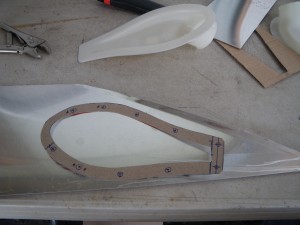
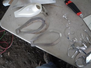
I wanted to make an aluminum backup ring so that the plastic part would be sandwiched between two layers of aluminum. The cardboard template made that step easy.
I drew a few lines on the boot cowl to try and figure out where I wanted to put the vent. My primary goals were to make the centerline of the intake horizontal in level flight, and to keep the intake lower than the outlet inside, so that water would be more likely to drain out if we were flying in the rain. I’m curious to see if this works. Note from the future! This vent installation is wrong. The hole is cut to the wrong shape- the aft portion of the vent should be straight across, not rounded.
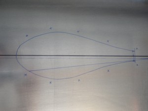
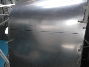
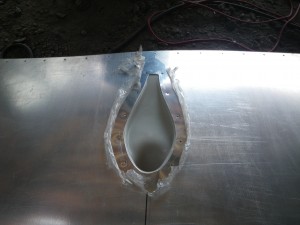
See note above- this is wrong. The aft side of the hole should be a straight line. I didn’t realize this until I was looking at Patrick’s RV in November 2010.
I got to the point of dimpling the holes for the first side and had to quit for the day.