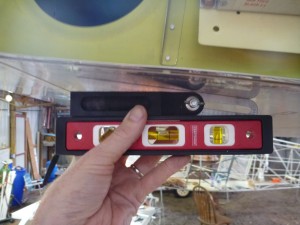
Today I spent a few hours of my birthday doing one of my favorite things, building airplanes. While I had the airplane leveled for wing measurements, I installed the Dynon compass sensors. The Dynon instructions say that the compass sensors and the D100-series units should be aligned within one degree or better. I’m using two compass sensors, one for the D180 and one for the D100. This will provide redundancy in the event of any number of small failures. I attached the two units together with brass screws and brass nuts. The brackets are built out of aluminum, so there aren’t any ferrous parts around. To start, I positioned the airplane so to be level left-right, and so that the bottom of the D180 mounting tray was level front-back. Then I used an angle measuring gauge and the level to find out what angle I needed to have between the wing bottom skin and the bottom of the sensor.

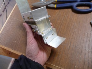
With that measurement in hand, I attached the little foot bracket to the inboard side of the stack. It would have looked cleaner to have a single piece of metal bent to form this part, but it would have been very difficult to get the angles just right. In this case, I drilled one hole and installed a cleco, then adjusted the angle, clamped the parts together, and drilled the second hole through both at the same time. The horizontal portion of this “foot” will be riveted to the wing skin. The inboard side of the bracket will be riveted to the tip rib, so it doesn’t need a foot.

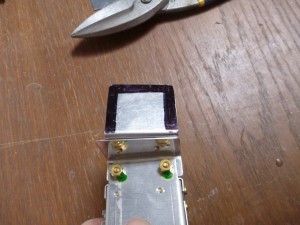
The next challenge was finding a way to drill the wing skin to match up with that foot. The easiest way would have been to drill down from the top, but there isn’t enough room in there for a drill. Instead, I drilled the holes in the skin first, based on an approximation of where they needed to go. Then I marked the edges of the foot so that I would be sure that I was close enough to the middle to avoid edge distance issues.

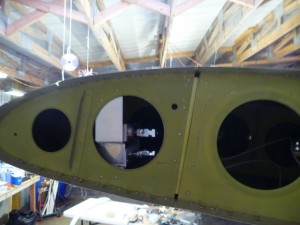
I put the whole assembly into the wing, then scooted it around until I could see aluminum through the holes, but no black marks. Then I aligned the assembly in the other axes, and match drilled the foot through the holes in the wing skin. Then I added two rivets above and two rivets below the units on the tip rib. The whole thing is lined up very well and feels plenty sturdy.
Note from the future: This installation is not correct, since I have the wires coming out of the back of the unit. The heading indicated 180 degrees off in this arrangement. Be sure to mount yours the right way!

I also added another layer of filler to the intake scoop and windshield fairing, again.