I deburred the lightening holes in the electrical panel, and removed all of the sharpie ink from layout planning.
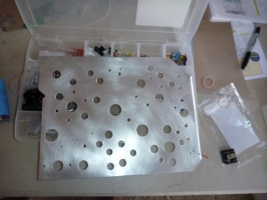
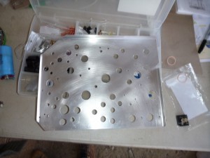
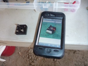
Next it was time to get to work populating that panel. I started with the diode bridge for the SD8 circuit.
First up is the resistor:
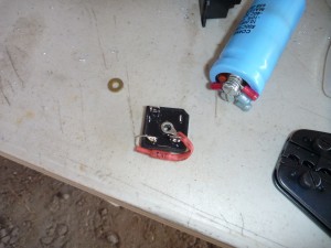
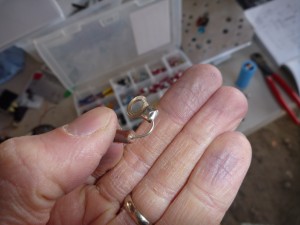
Here’s the resistor for the capacitor:
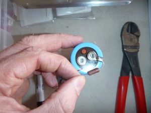
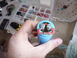
Here are most of the other components:
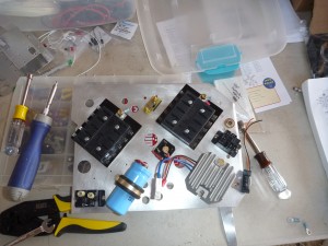
From left to right, top to bottom: Main bus fuse block, ebus diode, ebus fuse block, alternator diagnostic plug (later removed), SD-8 Diode Bridge, ebus relay, SD-8 Relay, SD-8 Capacitor, SD-8 Regulator, and SD-8 Crowbar overvoltage module.
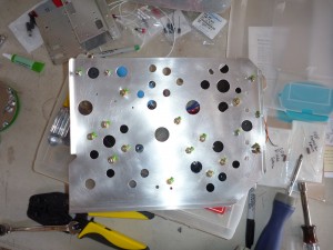
And the back:
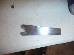
I’m attaching that panel to the fuselage tubes with adel clamps, so I thought I’d make a copy of a tool to help install those clamps. The V on the end goes into the threads of the bolt that secures the clamps, relieving tension on the nut after compression. That makes a 3 hand job into a 2 hand job.
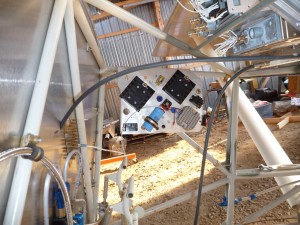
Here’s the panel in place. I didn’t realize at the time, but it’s going to crowd the duct for the right front seat passenger vent.
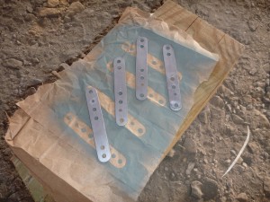
Since the weather was nice I also cleaned and primed the steel straps that connect the rudder cables to the rudder pedals.
