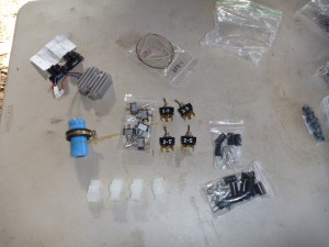
Today I started with an inventory of parts for the electrical system.
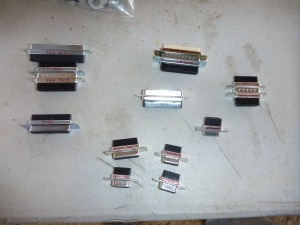
I’m using several d-sub connectors for the avionics, so I set them all out and wrote notes about which one needs to go where.
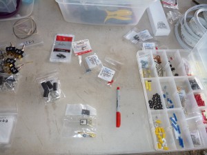
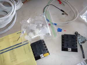
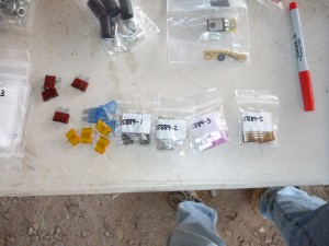
Now it’s time to put some of those new parts to work! First, I installed the switches.
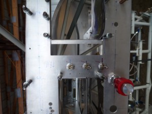
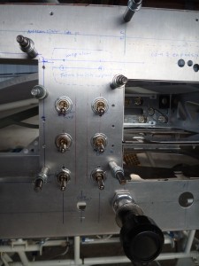
The switches are divided by function, with lights on the right, and the others on the left. Both banks are within comfortable reach from the left or right seat.
I spent a little bit of time getting the tip of my soldering iron reshaped and tinned, and fixed the AEC 9005 Low Voltage Warning Module. This is the one that I built per the Bob Nuckolls design. It wasn’t working after I first made it, but that was because I put a few parts in the wrong place. After I had all of that sorted out, it works great with my test harness hooked to the truck battery. This module is very simple and useful- it flashes a red LED whenever the master switch is on but the alternator isn’t. It’s important for the pilot to be aware of such a condition, because in flight it means that the alternator has quit and the system is consuming finite battery power. On the ground after shutdown it is a flashing reminder to turn the master switch off.
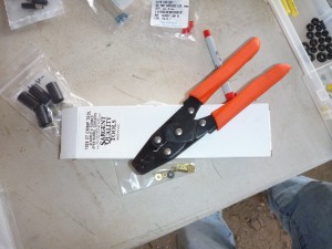
I wasn’t happy with the crimp results I was getting on larger electrical cables, so I’ve tried another method. The underlying problem is that the terminals are much larger than the conductor of the cable.
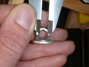
Bob Nuckolls suggested that I stick copper wedges into the strands to tighten the fit, then crimp or solder. An alternate technique that I tried was removing material from the terminal to reduce its inner diameter. This provided a snug fit, then I soldered the able to make the joint gas tight.
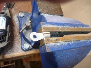
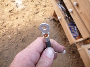
This method produced a much better product.
Danny was borrowing a set of scales, so we figured since they were at the airport we should go ahead and weigh the Bearhawk as it is.
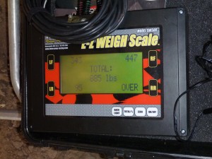
If I had a set of scales like this around all the time, I think it would be an interesting experiment to weigh the airplane weekly to see how it becomes so heavy. We’ll likely add another 400-500 pounds before we’re done. I also took a couple of overview shots since I didn’t have any good pictures with the wings on.
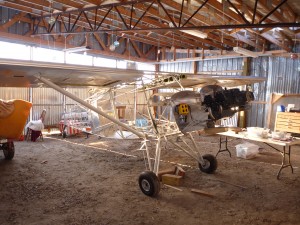
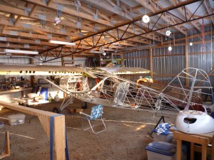
These pictures will mean a lot when the airplane is finished.